'Recognizing the need is the primary condition for design.'

Charles Eames

'To design is to communicate clearly by whatever means you can control or master.'
Milton Glaser

Motion Sensor Alarm with LCD, LEDs and Buzzer. 

Components Required: 


1X PIR sensor

1X Passive buzzer

1X Red LED
1X Green LED

2X Switches (Push type) 

1X LCD 16 X 2 screen with 4 pin interface

2 X 10k resistor


1 X Ardunio or Eligoo Mega or Uno Micro controller 

1X Breadboard

Wiring Instructions:

Use the inmstructions below with the image gallery to connect the components as follows:


PIR Sensor
1. Connect the PIR motion sensor's OUT (middle pin) pin to digital pin 2 of the Arduino Mega.


Buzzer
2. Connect one terminal of the buzzer to digital pin 3 of the Arduino Mega. Connet the other terminal to ground (GND)


LED's
3. Connect one terminal of each LED to digital pins 4 and 5 of the Arduino Mega. .

4. Connect the other terminal of each LED to GND (ground) of the Arduino Mega, using a resistor in series if required (depending on the LED specifications).


Switches
5. Connect one terminal of the arm switch to digital pin 6 of the Arduino Mega. (make sure the switch is pushed in the right way into the bread board (check images) 

6. Connect the other terminal of the arm switch to GND.


7. Connect one terminal of the reset switch to digital pin 7 of the Arduino Mega.

8. Connect the other terminal of the reset switch to GND.


LCD screen
9. Connect the LCD screen's SDA pin to the SDA pin of the Arduino Mega (usually A4).
10. Connect the LCD screen's SCL pin to the SCL pin of the Arduino Mega (usually A5).
11. Connect the LCD screen's VCC pin to the 5V pin of the Arduino Mega.
12. Connect the LCD screen's GND pin to the GND of the Arduino Mega.
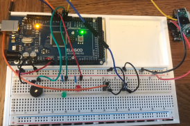
 

Use the image libary below to help you set the circuit up, hover mouse over each image for instructions;

Use the code below or in the file at the bottom of the page:

#include <Wire.h>
#include <LiquidCrystal_I2C.h>
 
LiquidCrystal_I2C lcd(0x3F, 16, 2); // Initialize the LCD with its I2C address, columns, and rows. N.B.  the LCD libary address could be different
 
#define PIR_PIN 2 // PIR motion sensor pin
#define BUZZER_PIN 3 // Buzzer pin
#define LED1_PIN 4 // LED 1 pin
#define LED2_PIN 5 // LED 2 pin
#define ARM_PIN 6 // Arm switch pin
#define RESET_PIN 7 // Reset switch pin
 
bool isArmed = false; // Alarm armed status
 
void setup() {
lcd.backlight();           // Turn on backlight
lcd.init();  // initialize the lcd
lcd.clear(); // clear the lcd
lcd.setCursor(0, 0);
lcd.print("  Press to Arm   ");
 
pinMode(PIR_PIN, INPUT); // Set the PIR motion sensor pin as an input
pinMode(BUZZER_PIN, OUTPUT); // Set the buzzer pin as an output
pinMode(LED1_PIN, OUTPUT); // Set LED 1 pin as an output
pinMode(LED2_PIN, OUTPUT); // Set LED 2 pin as an output
pinMode(ARM_PIN, INPUT_PULLUP); // Set arm switch pin as an input with internal pull-up resistor
pinMode(RESET_PIN, INPUT_PULLUP); // Set reset switch pin as an input with internal pull-up resistor
}
 
void loop() {
if (digitalRead(ARM_PIN) == LOW && !isArmed) { // Check if arm switch is pressed and alarm is not armed
isArmed = true; // Arm the alarm
lcd.setCursor(0, 0);
lcd.print("Burglar Alarm      ");
lcd.setCursor(0, 1);
lcd.print("Armed      ");
}
 
if (digitalRead(RESET_PIN) == LOW) { // Check if reset switch is pressed
isArmed = false; // Disarm the alarm
lcd.clear();
lcd.setCursor(0, 0);
lcd.print("Alarm Disarmed");
lcd.setCursor(0, 1);
lcd.print("Press Arm");
}
 
if (isArmed && digitalRead(PIR_PIN) == HIGH) { // Check if the alarm is armed and motion detected by the PIR sensor
tone(BUZZER_PIN, 1000); // Activate the alarm sound
digitalWrite(LED1_PIN, HIGH); // Turn on LED 1
digitalWrite(LED2_PIN, LOW); // Turn off LED 2
} else {
noTone(BUZZER_PIN); // Deactivate the alarm sound
digitalWrite(LED1_PIN, LOW); // Turn off LED 1
digitalWrite(LED2_PIN, HIGH); // Turn on LED 2
}
}
Arduino IDE code
Motion sensor FIN code.rtf
Text document [76.5 KB]
Print | Sitemap
© Julian Kupper