'Recognizing the need is the primary condition for design.'
Milton Glaser
Stepper motor control with pot and LEDs
Components Required:
1 X Stepper motor
1 X Stepper motor control board
1 X Potentiomter
3 X 10k resistors
1 X Red LED
1 X Green LED
1 X Micro controller board
Wiring Instructions:
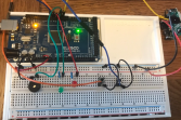
Use the instructions below with the image gallery to connect the components as follows:
5V + and - GND power from micro controller board to breadboard
1: Connect the 5V+ on the mega board to the + red rail on the breadboard, then connect the GND on the mega board to the - blue rail on the breadboard.
Stepper Motor and Stepper motor board
2: Connect the + and - on the Stepper motor controler board to 5V+ and 0V- rails on the bread board
Stepper motor to Stepper motor board
2.1: Connect the 4 wire motor cable from the stepper motor into the ABCD connector of the stepper controller boards
2.2: Connect the IN1, IN2, IN3, IN4 connectors on the stepper motor control board to Pin2,3,4, and 5 on the micro controller board.
Potentiometer / Variable resistor
3. Connect one terminal (left) of the potentiometer to +5V rail on the bread board, then connect the other terminal (right)
of the potentiometer to the 0v- rail of the breadboard, then connect a resistor between the 0v- right terminal pin of the potentiometer. (this protects the
potentiometer)
Then, connect the 'wipe' (middle connector) of the potentiometer to analogue Pin A0 on the micro controller board.
LEDs
4: Connect the short - leg of the red and green resistors to the -0V rail of the breadboard, then connect the positive leg of the LEDs to the breadboard with a resistor before connecting the positive leg of the red LED from the breadboard to pin 13 and the positive leg of the green LED to pin 12 on the micro controller.


