
'Recognizing the need is the primary condition for design.'
Milton Glaser
Unit 6 Electrical and Electronic Principles
Adobe Acrobat document [745.1 KB]

On completion of this unit a learner should:
1 Be able to use circuit theory to determine voltage, current and resistance in direct current (DC) circuits
2 Understand the concepts of capacitance and determine capacitance values in DC circuits
3 Know the principles and properties of magnetism
4 Be able to use single-phase alternating current (AC) theory.
Grading criteria for this module:


P1 & P2 Use DC circuit theory to calculate current, voltage and resistance in a DC network.

Fig 1: Battery powering two light bulbs of unequal resistance.
When current is flowing through the light bulb, the resistance of the filament causes a loss of voltage that is proportional to the resistance and the amount of current. We refer to this as the voltage across the bulb or as the bulb’s voltage drop.

Fig 2: Voltmeters are used to measure the voltage across the light bulbs
We see that the voltage across light bulb A is 2V and the voltage across light bulb B is 1V.
Next, we’ll measure the current.

Fig 3: Figure 5. Inset an ammeter such that the current flowing through the light bulbs flows into one probe, through the device’s current-measuring circuitry, and out the other probe.
Let’s assume that we measure 1A. We have now made the measurements that we need in order to determine the power dissipation of the light bulbs.
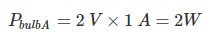
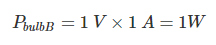
How to calculate the power dissipated by each light bulb.
Insert the measured values into the formula given above.
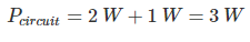
If we want to know the power dissipated by the entire circuit, we add up the power dissipation of the individual components:
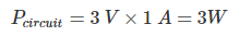
Or, we can multiply the current supplied from the battery by the battery’s voltage:
Below is an introduction to Ohm’s law, which expresses the fundamental relationship between current, voltage, and resistance.
June 2020
P3 Compere the forward and reverse charachteristics of two different types of semi conductor diode.
A diode is two terminal electronics component, which can be connected to the source in two different ways; Forward Bias and Reverse Bias. The forward bias works like a closed switch and allows the current through itself. In contrast to forward bias, the reverse bias connection blocks the current passage and works as an open switch. The biasing of a diode depends upon the direction of the source. Ref: https://electric-shocks.com/forward-and-reverse-bias-of-diode-explained-by-v-i-characteristic-curves/


Below are three diagrams that describe forward and reverse charachteristics of diodes.


P4 Types and functions of capacitors

Polar and Non-Polar Capacitor:
Capacitor applications in AC systems:
Capacitors in DC Circuits and systems:
P5 & P6 Carry out an experiement to determine the relationship between and charging and discharging capacitor.
P7 Describe the characteristics of a magnetic field
P8 Describe the relationship between flux density and field strength

As previously mentioned, permeability (m) is a material property that describes the ease with which a magnetic flux is established in a component. It is the ratio of the flux density (B) created within a material to the magnetizing field (H) and is represented by the following equation: m = B/H
|
|


The shape of the hysteresis loop tells a great deal about the material being magnetized. The hysteresis curves of two different materials are shown in the graph.
Relative to other materials, a material with a wider hysteresis loop has:
- Lower Permeability
- Higher Retentivity
- Higher Coercivity
- Higher Reluctance
- Higher Residual Magnetism
Relative to other materials, a material with the narrower hysteresis loop has:
- Higher Permeability
- Lower Retentivity
- Lower Coercivity
- Lower Reluctance
- Lower Residual Magnetism.
In magnetic particle testing, the level of residual magnetism is important. Residual magnetic fields are affected by the permeability, which can be related to the carbon content and alloying of the material. A component with high carbon content will have low permeability and will retain more magnetic flux than a material with low carbon content.
In the two B-H loops above, which one would indicative of a low carbon steel??
ref: http://www.nde-ed.org/EducationResources/CommunityCollege/MagParticle/Physics/Permeability.htm
M1 - use Kirchhoff’s laws to determine the current in various parts of a network having four nodes and the power dissipated in a load resistor containing two voltage sources
What is a load resistor in circuit?
Below are those things that can be load resistance:
1) Simple resistor
2) Audio speakers
3) LED lights
4) All types of the light indicator
5) Resistive sensors
6) Buzzers
7) The output stage of the radio frequency amplifier or audio frequency amplifier.
8) Antennas
9) High wattage resistor


Example of a 4 node circuit with 2 voltage sources you could use to design and simulate a circuit for M1

M2 - evaluate capacitance, charge, voltage and energy in a network containing a seriesparallel combination of three capacitors

Series, Parallel and Series / Parallel combination circuit to use in your simulations and calculations for M2
Useful calculators for charge. capatacence, voltage and energy.
https://www.gigacalculator.com/calculators/capacitor-charge-calculator.php
https://www.electronics2000.co.uk/calc/capacitor-charge-calculator.php